User slendercam1 uploaded the image
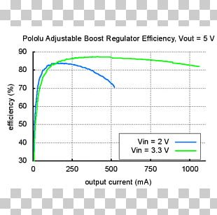
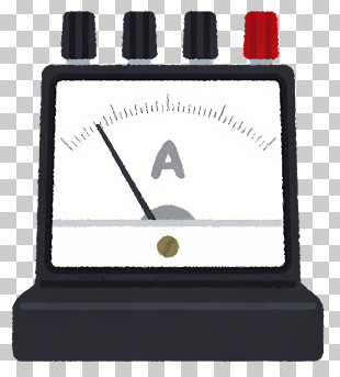
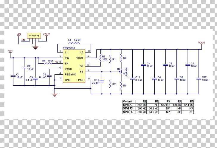
A circuit diagram of a DC to DC converter. It consists of several components such as resistors, capacitors, transistors, and diodes. The main component of the circuit is a voltage regulator, which is used to regulate the voltage in the circuit. The voltage regulator is connected to the resistors and capacitors. The transistors are used to power the circuit, while the diode is used as a power supply. There are also several other components in the diagram, including a voltage transformer, a resistor, and a capacitor. The diode has a voltage of 1.2 ohms, which can be used to control the voltage. The capacitor has a current of 0.1 ohms and a voltage voltage of 2 ohms. The circuit also has a resistor and a resistor that can be connected to other components, such as capacitors and resistors. - There is also a voltage indicator on the left side of the diagram that shows the current and voltage levels. This indicates that the circuit can be adjusted to different levels of voltage, allowing the user to adjust the voltage to their desired level.
Electric Potential Difference Voltage Regulator Electric Current Pololu Robotics And Electronics PNG
. The resolution of this PNG file is 700 x 500 pixels and it has a file size of 56.95 KB.A circuit diagram of a DC to DC converter. It consists of several components such as resistors, capacitors, transistors, and diodes. The main component of the circuit is a voltage regulator, which is used to regulate the voltage in the circuit. The voltage regulator is connected to the resistors and capacitors. The transistors are used to power the circuit, while the diode is used as a power supply. There are also several other components in the diagram, including a voltage transformer, a resistor, and a capacitor. The diode has a voltage of 1.2 ohms, which can be used to control the voltage. The capacitor has a current of 0.1 ohms and a voltage voltage of 2 ohms. The circuit also has a resistor and a resistor that can be connected to other components, such as capacitors and resistors. - There is also a voltage indicator on the left side of the diagram that shows the current and voltage levels. This indicates that the circuit can be adjusted to different levels of voltage, allowing the user to adjust the voltage to their desired level.
Electric Potential Difference Voltage Regulator Electric Current Pololu Robotics And Electronics PNG
You might also like...