User FAIS_13ATTENTION uploaded the image
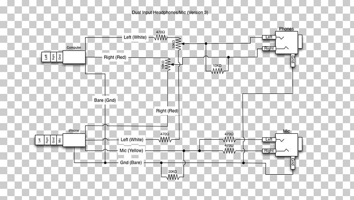
A circuit diagram of a dual input headphone amplifier. It consists of three components: a left (white), a right (red), and a gnd (bare). The left component is connected to the right component, which is represented by a black rectangular box with a white label that reads "Left (White)". The right component is also connected to a black rectangle with a red label that says "Right (Red)". There are two other components in the diagram, one on the left side of the diagram and the other on the right side. These components are connected by a series of wires and connectors. In the center of the image, there is a small circuit with two resistors, one in white and one in red. The resistors are connected to two capacitors, one at the top and one at a bottom, which are used to power the amplifier. The capacitors are also connected by two wires, which act as capacitors in the circuit. The circuit also has a few other components, such as a resistor and a capacitor, which can be used to connect the two components together. The diagram also shows how the amplifier works and how they interact with each other.
Microphone Wiring Diagram Phone Connector Headphones Electrical Wires & Cable PNG
. The resolution of this PNG file is 972 x 553 pixels and it has a file size of 30.71 KB.A circuit diagram of a dual input headphone amplifier. It consists of three components: a left (white), a right (red), and a gnd (bare). The left component is connected to the right component, which is represented by a black rectangular box with a white label that reads "Left (White)". The right component is also connected to a black rectangle with a red label that says "Right (Red)". There are two other components in the diagram, one on the left side of the diagram and the other on the right side. These components are connected by a series of wires and connectors. In the center of the image, there is a small circuit with two resistors, one in white and one in red. The resistors are connected to two capacitors, one at the top and one at a bottom, which are used to power the amplifier. The capacitors are also connected by two wires, which act as capacitors in the circuit. The circuit also has a few other components, such as a resistor and a capacitor, which can be used to connect the two components together. The diagram also shows how the amplifier works and how they interact with each other.
Microphone Wiring Diagram Phone Connector Headphones Electrical Wires & Cable PNG
You might also like...