User naillounge uploaded the image
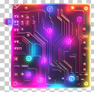
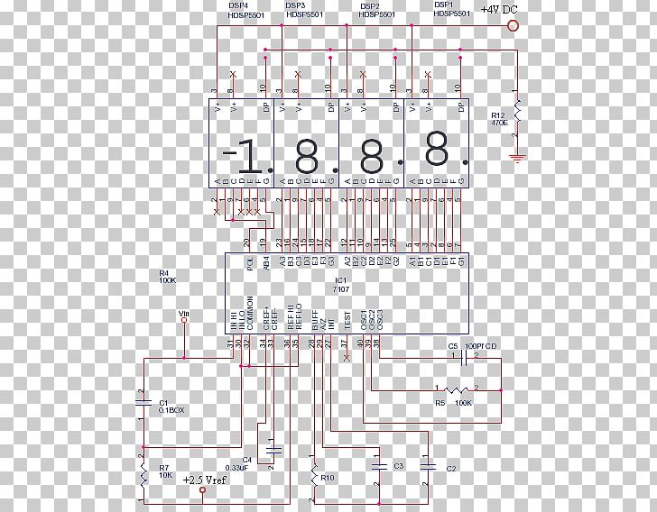
A circuit diagram of a DC to DC converter. It consists of a 1.8.8 power supply, a DC-DC converter, and various components such as resistors, capacitors, transistors, and diodes. The main component of the circuit is the DC converter, which is connected to a DC motor. The DC motor is used to control the voltage and current in the circuit. The resistors are used to power the DC motor, while the capacitors and transistors are used for controlling the voltage. There are also several other components in the diagram, such as a resistor, a capacitor, and a resistor. These components are connected by lines and arrows, indicating the direction of the current flow. The circuit also has a resistor and a capacitor connected to it, which can be used to connect the DC to the DC power supply. The resistor is used as a power supply for the DC DC converter and the capacitor is used for the power supply to power it. The diode is also used to convert the voltage from DC to AC, which means that the circuit can be controlled by using the resistor and capacitor.
Electronic Circuit Circuit Diagram Temperature Control Electronics Schematic PNG
. The resolution of this PNG file is 445 x 572 pixels and it has a file size of 6.10 KB.A circuit diagram of a DC to DC converter. It consists of a 1.8.8 power supply, a DC-DC converter, and various components such as resistors, capacitors, transistors, and diodes. The main component of the circuit is the DC converter, which is connected to a DC motor. The DC motor is used to control the voltage and current in the circuit. The resistors are used to power the DC motor, while the capacitors and transistors are used for controlling the voltage. There are also several other components in the diagram, such as a resistor, a capacitor, and a resistor. These components are connected by lines and arrows, indicating the direction of the current flow. The circuit also has a resistor and a capacitor connected to it, which can be used to connect the DC to the DC power supply. The resistor is used as a power supply for the DC DC converter and the capacitor is used for the power supply to power it. The diode is also used to convert the voltage from DC to AC, which means that the circuit can be controlled by using the resistor and capacitor.
Electronic Circuit Circuit Diagram Temperature Control Electronics Schematic PNG
You might also like...