User SpenserWithAnS uploaded the image
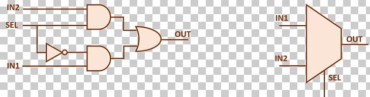
A circuit diagram of an IN2 (IN2) and SEL (SEL) circuit. The IN2 circuit consists of two resistors, IN1 and IN2, connected by a series of wires. In the IN1 circuit, there are two capacitors, IN2 and OUT, which are connected to each other. In the OUT circuit, the IN2 capacitors are connected in a way that they form a waveform. The OUT circuit is also connected to the IN3 capacitors. On the right side of the image, there is a SEL circuit, which is a type of electronic component that is used to control the flow of data between two components. This circuit is typically used in a computer or other electronic device to monitor and control the current and voltage in the circuit.
Multiplexer Electronic Circuit AND Gate Input Signal PNG
. The resolution of this PNG file is 1552 x 417 pixels and it has a file size of 9.20 KB.A circuit diagram of an IN2 (IN2) and SEL (SEL) circuit. The IN2 circuit consists of two resistors, IN1 and IN2, connected by a series of wires. In the IN1 circuit, there are two capacitors, IN2 and OUT, which are connected to each other. In the OUT circuit, the IN2 capacitors are connected in a way that they form a waveform. The OUT circuit is also connected to the IN3 capacitors. On the right side of the image, there is a SEL circuit, which is a type of electronic component that is used to control the flow of data between two components. This circuit is typically used in a computer or other electronic device to monitor and control the current and voltage in the circuit.
Multiplexer Electronic Circuit AND Gate Input Signal PNG
You might also like...