User j4s0n uploaded the image
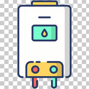
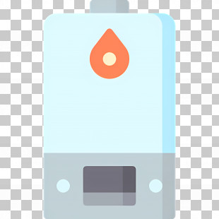
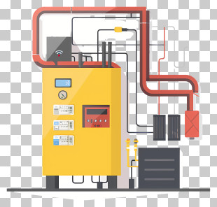
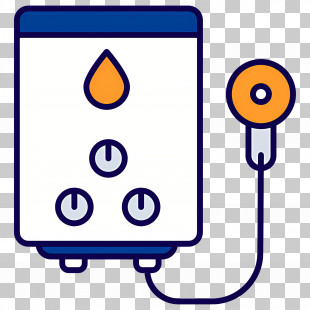
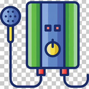
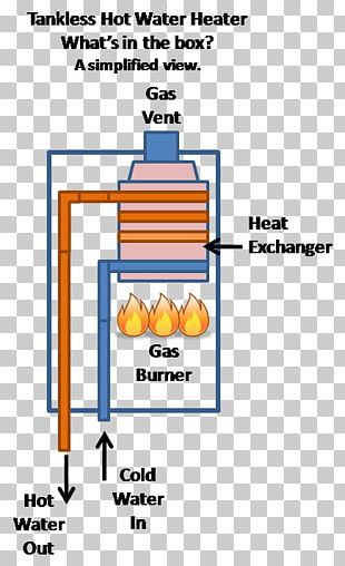
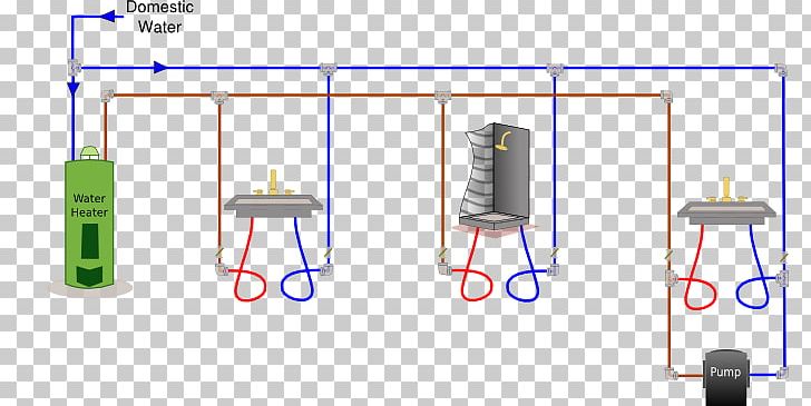
A diagram of a water heater system. It consists of three components: a green water heater, a black water tank, and a pump. The water heater is on the left side of the image, with a green cylinder on top and a black tank on the right side. The water tank is connected to the pump via a series of pipes and wires. The pipes are arranged in a horizontal line, with the water tank at the top and the pump at the bottom. There are two red and blue wires connecting the two components. The red wires are connected to a black and white water tank with a yellow valve. The yellow valve is located on the top of the tank and is used to control the flow of water from the water to the tank. The blue wires are used to connect the pipes and valves to the water heater. The diagram also shows how the water is flowing through the pipes, creating a flowchart-like effect.
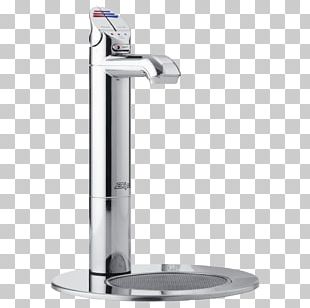
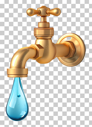
Circulator Pump Tankless Water Heating Instant Hot Water Dispenser Faucet Handles & Controls PNG
. The resolution of this PNG file is 702 x 369 pixels and it has a file size of 36.17 KB.A diagram of a water heater system. It consists of three components: a green water heater, a black water tank, and a pump. The water heater is on the left side of the image, with a green cylinder on top and a black tank on the right side. The water tank is connected to the pump via a series of pipes and wires. The pipes are arranged in a horizontal line, with the water tank at the top and the pump at the bottom. There are two red and blue wires connecting the two components. The red wires are connected to a black and white water tank with a yellow valve. The yellow valve is located on the top of the tank and is used to control the flow of water from the water to the tank. The blue wires are used to connect the pipes and valves to the water heater. The diagram also shows how the water is flowing through the pipes, creating a flowchart-like effect.
Circulator Pump Tankless Water Heating Instant Hot Water Dispenser Faucet Handles & Controls PNG
You might also like...