User vp25 uploaded the image
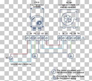
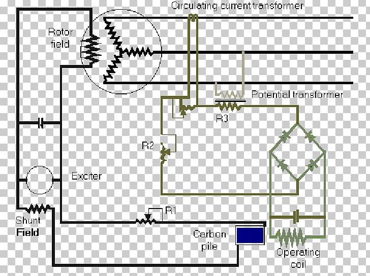
A circuit diagram of a current transformer. It consists of a rotor field, a potential transformer, an exciter, a shunt field, and an operating coil. The rotor field is connected to the potential transformer and the exciter is located in the center of the circuit. The potential transformer is located on the right side of the image. The exciter and the operating coil are located at the bottom right corner. There is also a carbon pile in the bottom left corner, which is used to collect the current from the rotor field. The carbon pile is located near the rotor and is used as a source of energy for the current. The operating coil is located to the left of the rotor, where the current is passed through the rotor. The circuit also has several resistors and capacitors connected to it, which are used to power the current and prevent it from overheating.
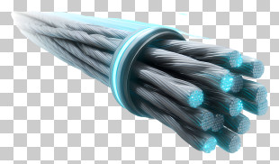
Voltage Regulator Electric Potential Difference Electrical Wires & Cable Alternating Current PNG
. The resolution of this PNG file is 704 x 548 pixels and it has a file size of 10.93 KB.A circuit diagram of a current transformer. It consists of a rotor field, a potential transformer, an exciter, a shunt field, and an operating coil. The rotor field is connected to the potential transformer and the exciter is located in the center of the circuit. The potential transformer is located on the right side of the image. The exciter and the operating coil are located at the bottom right corner. There is also a carbon pile in the bottom left corner, which is used to collect the current from the rotor field. The carbon pile is located near the rotor and is used as a source of energy for the current. The operating coil is located to the left of the rotor, where the current is passed through the rotor. The circuit also has several resistors and capacitors connected to it, which are used to power the current and prevent it from overheating.
Voltage Regulator Electric Potential Difference Electrical Wires & Cable Alternating Current PNG
You might also like...